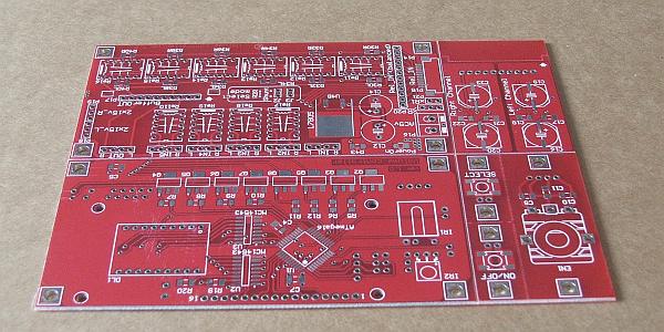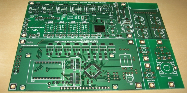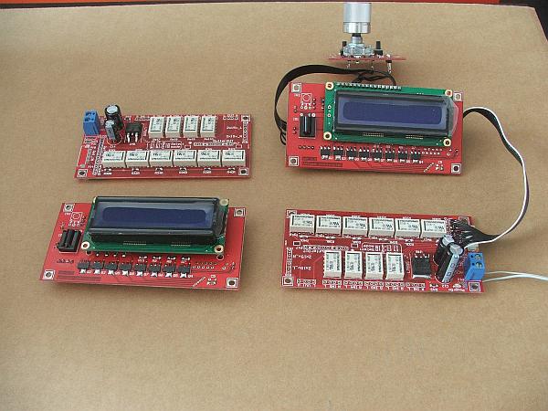
R-2R / SHUNT VOLUME CONTROLLER with 4 selectable sources
Schematic, bom,
firmware, Bascom source code, documentation and gerber files are
available below.
This documentation is Open Hardware and is licensed under the CERN OHL v. 1.2.
You may redistribute and modify this documentation under the terms of the CERN OHL v.1.2. (http://ohwr.org/cernohl). This documentation is distributed WITHOUT ANY EXPRESS OR IMPLIED WARRANTY, INCLUDING OF MERCHANTABILITY, SATISFACTORY QUALITY AND FITNESS FOR A PARTICULAR PURPOSE. Please see the CERN OHL v.1.2 for applicable conditions
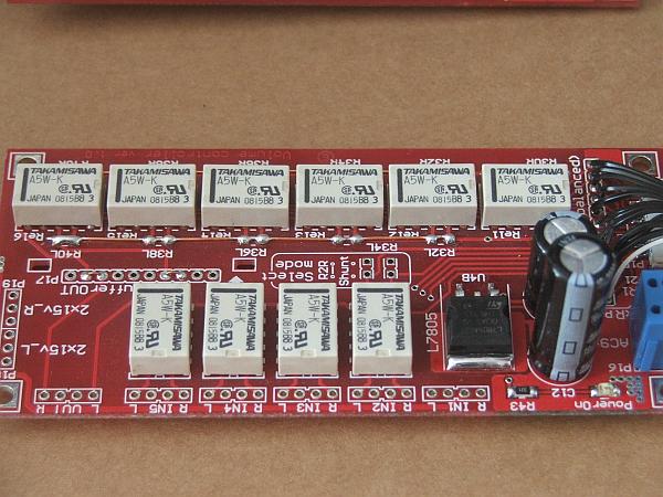
R2R volume controller offer important sonic advantages over common potentiometers due of discrete resistors and method of signal attenuation: resistor voltage dividers. Discrete resistors offer better low noise and characteristics than the carbon or cermet resistor elements used in potentiometers. R2R volume controller make use of low tolerance, noninductive, professional MELF resistors for R-2R/Shunt attenuation network.
MELF is the acronym for Metal Electrode Leadless Face - a leadless cylindrical component that is metallized on two ends. It is designed majorly as a SMD (Surface Mounting Device) component. Since manufacturing process of MELF resistor is more complex than flat-chip resistor, MELF resistor has its own advantages over flat-chip type.
Compared with regular flat-chip type SMD resistors, MELF offer low TCR (typical lower than ±5ppm/°C), greater surge handling, low noise and ultra low distorsion, ensuring high stability through time and over temperature variations.
The total measured resistance for each position of our volume-controller remains constant throughout years of use. This is because the wearing (rubbing) parts in R2R volume controller are low resistance switching relays, not resistive elements with wipers sliding on them as in potentiometers. Potentiometers can add clicks, pops, and noise to wear.
Stereo potentiometers used as volume controls often produce different volume levels for each channel, and the amount of mismatch can vary as the potentiometer is turned up or down. The channel-to-channel tracking specification for stereo potentiometers, even very expensive ones, is typically 5% to 20%. With this R2R volume controller you can easily achieve stereo signal levels matched up to 0.1%.
Outstanding S/N ratio and excellent THD of the amplifier is not compromised in any way, and the same superb sound quality will be obtained at any volume setting. Signal level has been pre-determined for each step, so front panel display can represent actual signal levels.


– low tolerance 0.1% R-2R network with melf resistors
– attenuation in 64 steps - each step 1dB
– Input resistance ranges from 20k to 1M for a Rload of 1M.
– Output resistance ranges from 9.75k to 10.5k.
– 4 selectable inputs with option to edit input name
– one direct input
– Infrared RC5 autolearning (can be used with any RC5 compatible universal remote)
– display back-light programmable On/Off - if Off timeout 10s
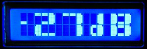
- large display characters for wide view
– tube menu for delaying plate voltage
– two open collector outputs for power On/Off and tube plate delay (see schematic J7 connector)
– AC power consumption, Max. 6W
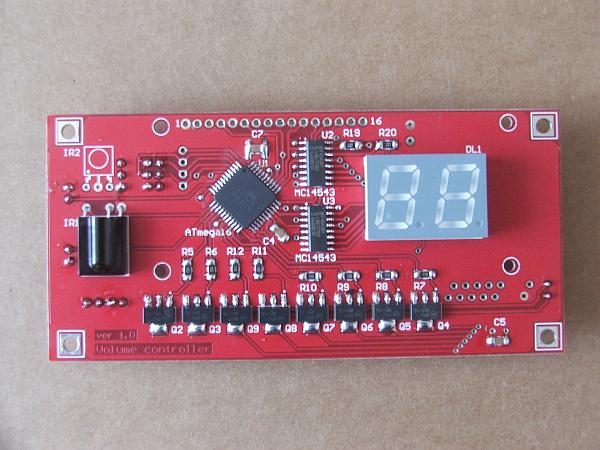
PCB board may support LCD or LED display up to the Atmel software.
R-2R resistor ladder network or shunt operation can be selected by using only one board jumper.
The boards are balanced or multichannel ready. That means you can control up to 8 relay boards with only one controller. A connector will allow you to easily cascade one board in top of other.
In order to decrease output impedance, an optional buffer with LME49600 can be plugged into relay board.
You can switch between 4 selectable sources and one direct input with no relay in signal path.
Standard input impedance is 20KOhm and can be adjusted by changing R-2R ladder network values up to your needs.

First Part_1 (historic page provided only as reference)
Second Part_2
(historic page provided only as reference)
LCD Atmega16 firmware ver.4.3 with all transistor onboard
LCD Atmega16 firmware ver.4.3 without all transistor onboard - trough zero implementation to completely remove any clicks and pops
LCD Atmega16 firmware ver.3.14
- corrected a bug with editing of 7th character in MENU
LCD Atmega16 firmware ver.3.12
- this is a bug fix release which address muting and menu edit feature
LCD Atmega16 firmware ver. 3.11
- this version implement large custom characters
for volume attenuation as per below image
- this will address a very
short display flikering, with this new version is completely gone
LCD Atmega16 firmware ver 3.8
- correct a problem with menu edit text
LCD Atmega16 firmware ver 3.5
- reduce substantially clicking noise due r-2r
relay operation
LCD Atmega16 firmware ver 1.0
- first public version
How
to program and update your Volume-Controller firmware.
How to set-up infrared remote controll for your Volume-Controller
Schematic - click image to download

Gerber files.

For stereo RCA`s use below setup
In case you are using a
balanced
volume-controller please refer to below setup. Each XLR use different
relay boards for IN+ and IN-. A better setup is presented in below
Balanced [2] picture
Second and the best
setup for balanced and multichannel is using each board for a balanced
chanel.
If you are mounting
volume controller in a pre/amplifier with a sigle ground star point,
connect 0ohm resistors R41L and R42R.